
Insert Molding Services

RpMolds offers expert insert molding services. Embed threaded brass inserts, structural pins, and electrical contacts directly into your injection-molded parts — eliminating secondary assembly and producing stronger, more reliable components in a single shot.
Brass · Stainless · Copper
M1.6 – M20 Thread Sizes
Free DFM Review
An NDA can be signed if needed before the quotation.
Insert Molding RpMolds

One Shot. Metal and Plastic Together.

Insert molding is an injection molding process where pre-formed metal components — threaded inserts, pins, shafts, or electrical contacts — are placed inside the mold cavity before the plastic is injected. The molten plastic flows around and mechanically locks to the insert, producing a single integrated part.

The result combines the structural strength and wear resistance of metal with the design flexibility and light weight of plastic — in one manufacturing step, with no secondary assembly operations required.

Benifit of Insert Molding

Eliminates secondary assembly

Inserts are captured in the mold — no press-fitting, ultrasonic welding, or post-molding installation needed

Threaded brass inserts achieve 500–1,200 N pull-out force, versus 80–200 N for self-tapping into plastic

Replace machined metal housings with plastic bodies and metal only where needed — typical weight reduction of 30–60%

Multiple components consolidated into one molded assembly — fewer suppliers, less inventory, simpler logistics

Critical for products that require repeated assembly/disassembly without thread wear or stripping

Insert Molding with RpMolds

Four Categories of Inserts We Work With

Select a category to explore materials, dimensions, retention specs, and typical applications for each insert type we regularly process.

Threaded inserts
Standard Knurled Brass Insert
Size Range
M1.6 – M12
Pull-out Force
400 – 1,200 N
Torque Resist.
0.4 – 3.0 N·m
Insert Pos. Tol.
±0.05 mm
Threaded Inserts — The Most Common Insert Type
Threaded inserts are placed in the mold cavity and encapsulated by plastic during injection, creating a permanent metal thread in a plastic housing. They provide far superior thread integrity over self-tapping screws — especially in applications that require repeated assembly and disassembly without thread wear. Knurled outer surfaces and grooves create mechanical interlock against both rotation and pull-out forces.
Primary Materials
Brass (CuZn39Pb3) — Most Common Stainless Steel 304/316 Aluminum 6061
Applications
Electronics enclosures PCB standoffs Automotive interior trim Consumer appliances Instrument housings Power tool bodies Medical device panels

Design note: For optimal pull-out performance, the plastic wall surrounding the insert should be at least 1.5× the insert outer diameter. A well-designed M4 brass insert in PA66-GF30 achieves 700–900 N pull-out. Inserts must incorporate anti-rotation features (knurls, hex body, or grooves) — smooth cylindrical inserts will rotate under torque load.

Grooved Retention Pin
Diameter Range
Ø 2 – 50 mm
Length Range
5 – 200 mm
Positional Tol.
±0.08 mm
Materials
SS, Carbon Steel
Structural Pins, Shafts & Axles
Pins, shafts, and axles are overmolded to create load-bearing pivot points, alignment features, and wear-resistant contact zones within plastic assemblies. Unlike threaded inserts, these are primarily loaded in shear and bending rather than axial tension. Retention grooves or cross-holes provide mechanical interlocking against axial pull-out. The plastic encapsulation also serves as a bearing surface for rotating shaft applications.
Primary Materials
Stainless Steel 304/316 Carbon Steel + Zinc Plate Hardened Tool Steel Aluminum 6061
Applications
Hinge pins & pivot axles Gear shaft centers Alignment pins Wear-surface inserts Bearing bushings Roller cores Locking mechanisms

Design note: Shaft insert diameter should be ≥ the expected load / (allowable shear stress of plastic × engagement length). For rotating shafts, specify the bearing clearance — typically 0.05–0.15 mm for light loads in PA or POM. Grooves or cross-holes are essential for axial retention; smooth shafts will eject under vibration.

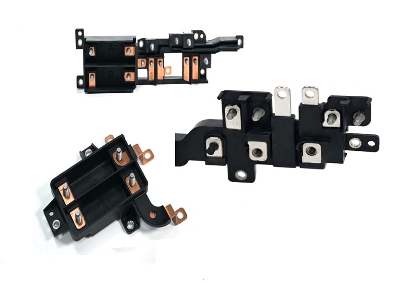
Electrical Contacts, Terminals & Leadframes
3-Pin Connector Terminal
Conductivity
High
Contact Resist.
< 5 mΩ
Positional Tol.
±0.03 mm
Materials
Copper, Brass
Electrical Contacts, Terminals & Leadframes
Electrical contacts and conductive inserts are overmolded to create integrated connector housings, terminal blocks, sensor probes, and PCB pin-headers. Positional accuracy is critical — even a 0.05 mm offset on a contact pin can cause intermittent connection or assembly rejection. We use precision mold seats and in-process verification for all electrical insert applications. Plating must withstand mold temperatures (typically 60–120°C) without delamination.
Primary Materials & Finishes
Copper C110 / C260 Brass CuZn37 Nickel-plated Steel Gold-plated (high freq.)
Applications
PCB pin headers Connector housings Battery terminals Sensor probes Leadframe encapsulation Grounding contacts RF antenna bases

Design note: Plastic materials for electrical applications must have appropriate dielectric strength and tracking resistance. PC, PBT, and PA66 are typical choices. Plating thickness affects insert dimensional tolerance — specify post-plating dimensions. Avoid silver plating in high-humidity environments (migration risk). Always specify the maximum mold temperature to verify plating compatibility.

Custom Metal Geometries Insert Molding
Custom Stamped Metal Bracket
Insert Source
Customer or RpMolds
Complexity
Unlimited shapes
Mass Range
0.5g – 500g
Tolerance
±0.1 mm typical
Custom Metal Geometries — Stampings, Brackets & Machined Parts
Any metal component with the right geometry can be insert molded — not just standard threaded inserts. Stamped brackets, machined parts, formed springs, wire terminals, and complex frame structures can all be placed in the mold and encapsulated in plastic. These applications are especially valuable for creating multi-material structural assemblies where the metal component provides load path and the plastic provides housing, guiding, or insulation.
Insert Manufacturing Methods
Metal Stamping CNC Machining Die Casting Powdered Metal Sintering
Applications
Structural frame encapsulation Gear hub assemblies Magnetic insert parts Sensor housings Valve body reinforcement Hermetic seal components Medical implant components

Design note: Customer-supplied inserts must meet dimensional tolerances that allow reliable mold seating (typically ±0.1 mm on seating surfaces). RpMolds can also design and source the metal inserts as part of your project. Provide functional requirements and assembly intent — we'll engineer the insert geometry and the mold pocket together to ensure reliable placement and retention.

Custom Metal Geometries Insert Molding

Materials for Insert Molding Applications

The plastic substrate must accommodate both the insert’s thermal expansion coefficient and the mechanical loads at the insert-plastic interface. These are our most commonly processed materials for insert molding.

PA6 / PA66
Nylon 6 / Nylon 66
Best for Threaded Inserts
High tensile strength (80–85 MPa), excellent fatigue resistance, good chemical resistance to oils and fuels. Low friction. GF30 grade significantly improves stiffness and insert pull-out.

Automotive, power tools, industrial fasteners

Polycarbonate
Electrical & Medical
Outstanding impact strength, optical clarity option, excellent dimensional stability. High mold temp (80–120°C) improves insert bonding. Sensitive to stress concentrations near sharp insert edges.

Electronics, medical devices, optical housings

Acrylonitrile Butadiene Styrene
Consumer Electronics
Good surface finish, easy to process, moderate strength. Widely used for consumer electronics enclosures with threaded brass inserts. Not suitable for high-temperature or load-bearing applications.

Enclosures, panels, consumer devices

Polyoxymethylene (Delrin / Acetal)
Precision Parts
Excellent dimensional stability, very low creep, low friction coefficient. Ideal for precision inserts and wear surfaces. Note: high shrinkage requires careful insert seat design to prevent cracking.

Gears, bearings, precision connectors

PC+ABS
Polycarbonate / ABS Blend
Automotive & Electronics
Balanced blend of PC impact resistance and ABS processability. Excellent for large, complex parts with multiple insert locations. Better low-temperature impact than ABS alone.

Automotive interior, electronics housings

Glass-filled Polypropylene
Structural / Cost-Efficient
Low cost, good chemical resistance, lightweight. GF10–GF30 grades provide the stiffness needed for reliable insert retention. PP has higher shrinkage — insert seat tolerance is critical.

Consumer goods, fluid handling, housewares

30% Glass-filled Nylon
Highest Load Capacity
The gold standard for high-load insert molded parts. Tensile strength up to 165 MPa, M4 insert pull-out exceeding 1,100 N. Low creep, excellent fatigue. Required for automotive structural applications.

Automotive structural, industrial equipment

Polybutylene / Ethylene Terephthalate
Electrical Grade
Excellent dielectric properties, high tracking resistance, good dimensional stability. Preferred for electrical connector housings and terminal blocks with copper or brass inserts.

Connector housings, terminal blocks, relays

Stainless Steel Insert Molding
Custom Metal Insert Molding

6 Rules for Reliable Insert Molded Parts

Insert molding introduces unique stress concentrations that don’t exist in standard injection molding. These guidelines prevent the most common failure modes — cracking, insert pull-out, and rotation.

1
Minimum Plastic Wall Around Insert
Min 1.5× Insert OD

The plastic surrounding an insert must be thick enough to bear the pull-out load. For a brass M4 insert (OD ~7 mm), the minimum plastic radius from insert center to nearest wall should be ≥ 10.5 mm. Thinner walls will crack under torque or thermal cycling.

2
Anti-Rotation Features Required
Knurls + hex body preferred

Every threaded insert must have mechanical anti-rotation features — knurled outer surface, hex body, or circumferential grooves. Smooth cylindrical inserts will spin under screw-driving torque regardless of the plastic's compressive grip.

3
Keep Weld Lines Away from Inserts
Min 3 mm clearance

Weld lines form where plastic flow fronts meet, creating a bond 20–40% weaker than the bulk material. Gate position should ensure weld lines form in low-stress regions — never bisecting an insert seat or boss structure.

4
Match Coefficients of Thermal Expansion
Brass: 19 ppm/°C · PA66: 80–130 ppm/°C

The large CTE mismatch between metals and plastics creates differential shrinkage stress around inserts. Design the boss wall thickness to accommodate this — and avoid materials with extreme CTE mismatch (e.g., POM around large steel shafts) unless the part operates in a narrow temperature range.

5
Specify Insert Seat Tolerances
Mold seat: ±0.03 mm typical

The mold seat (the locating feature that holds the insert in position during injection) must be tighter than the insert's own manufacturing tolerance. Specify the required insert positional accuracy in the finished part — we'll engineer backward to the mold seat tolerance and insert procurement spec.

6
Avoid Sharp Transitions at Insert Base
Min R0.5 at insert flange transition

Abrupt wall thickness changes at the insert base — especially at flanged inserts — create stress concentration points. Include a small radius (R0.5 minimum) at the transition between the insert flange and the plastic boss wall to distribute stress across a wider area.

Ready to Quote Your Insert Molding Project?

Upload your CAD file and we’ll return a quote within 24 hours — including a free DFM review that checks insert placement, wall thickness, and retention design before tooling starts.