
Design For Manufacturability (DFM)
RpMolds use the latest design for manufacturability (DFM) techniques to ensure that your parts are optimized for manufacturing – and to help control production costs and boost your profitability. Our senior engineer checks your CAD for wall thickness, draft angles, undercuts, and gate placement.
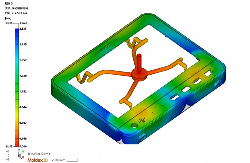
Parameters in Every Review
Each parameter maps to a real defect mode. Our engineers don’t just flag issues — they specify the exact fix required so revision rounds happen on screen, not in steel.
Wall Thickness
Uniform walls cool consistently and prevent sink marks and warpage. We flag walls outside ±15% of nominal and specify transition zones instead of abrupt steps.
Draft Angles
Every cavity face needs draft to release cleanly. Textured surfaces need 3–5°. We identify all zero-draft faces and specify the required angle based on depth and surface finish.
Boss Geometry
Gate Location
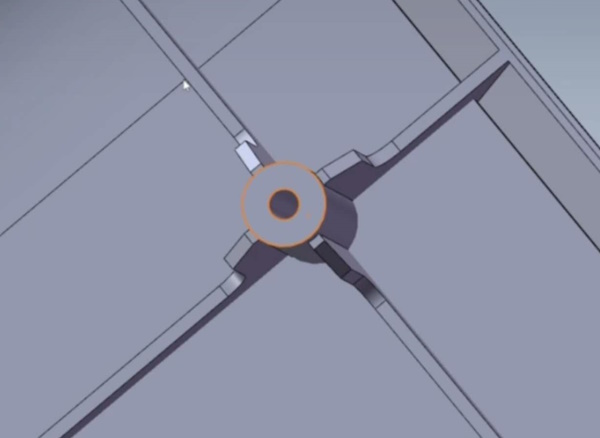
Gate position controls flow path, weld line location, and packing pressure. We review fill direction, mark predicted weld line positions, and confirm placement avoids Class-A surfaces.

Rib Design
Ribs add stiffness without adding mass. Oversized ribs always cause sink on the opposite face. We check thickness, height, base radius, and draft, and recommend gusset patterns where needed.

Undercuts
Undercuts require sliders or lifters that add cost and cycle time. We evaluate whether design changes can eliminate them, and specify the mold action type when they are genuinely required.
Parting Line
Parting line position affects cosmetics, flash risk, and ejection direction. We propose the optimal split plane considering functional surfaces, appearance requirements, and mold complexity.
Corner Radii
Sharp internal corners create stress hot spots that crack mold steel prematurely. Every internal corner needs at least 0.5 mm radius — ideally 0.5× wall thickness. We catch all violations.
Tolerances & Fit
We review all critical dimensions, mating interfaces, and snap-fit features. Precision zones (±0.05 mm) are called out with tooling strategy notes on how to hold them reliably in production.
Problems DFM Catches Before Machining
These are the defects that most commonly appear after mold cutting starts — when they’re 10× more expensive to fix. Our review catches every one before steel moves.
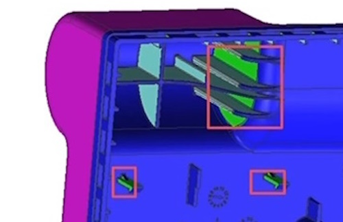
Boss wall 4.8 mm against a 2.0 mm nominal — 2.4× ratio guarantees sink on the A-surface opposite the boss
Hollow the boss, add gusset ribs to restore structural connection — eliminates the mass concentration
11 internal faces at 0° draft on a 58 mm deep cavity — part tears and marks on every ejection cycle
Add 1.5° draft to all cavity faces; increase to 3° on textured zones — adjust mating assembly interfaces accordingly
3 snap hooks require 3 individual side-actions — adds ~€2,400 to tooling cost and 0.4s to cycle time
Redesign 2 hooks as bump-off through-holes, retain 1 slider — eliminates 2 actions and saves ~€1,600 in tooling
Gate position routes a weld line directly through the hinge mounting boss — a high-stress cyclic-load interface
Move gate 16 mm toward center — weld line shifts to low-stress interior flat, no strength impact
230 × 175 mm panel, 1.8 mm wall, no ribs — predicted 1.3 mm bow in ABS after ejection, out of assembly tolerance
Add 3 cross-ribs at 58 mm pitch on rear face — stiffness increases 4×, bow reduced to under 0.3 mm
0.8 mm wall 98 mm from gate in PC/ABS — flow ratio 122:1 exceeds material capability, part will short-shot
Increase wall to 1.2 mm or add a second gate — flow ratio drops below 85:1 for reliable fill in production