
Overmolding Service for Multi-Material Parts
RpMolds bonds TPE, silicone, and rubber over rigid plastic or metal substrates. Full-service: substrate mold, overmold tooling, production, and DFM review — shipped to Europe and North America.
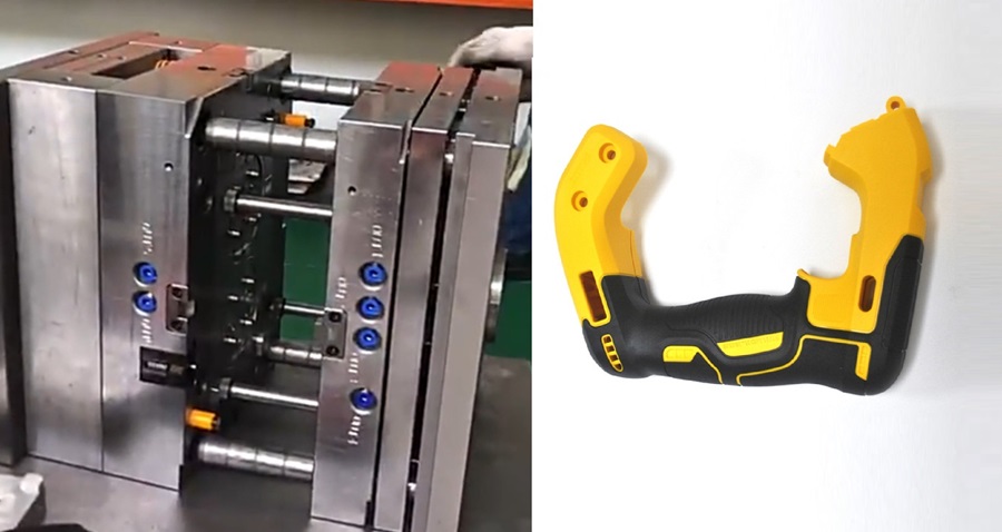
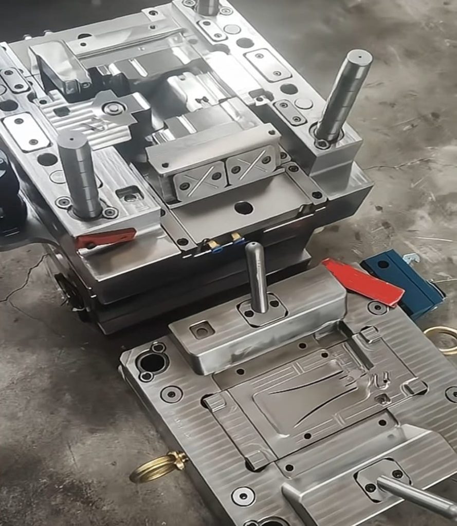
Overmolding Expertise From Xiamen
We’re a specialist mold manufacturer — not a general job shop. Our focus on precision tooling and repeatable production makes us the preferred China-based partner for European and North American B2B buyers.
Dedicated Engineering Team
Senior mold engineers with 10+ years in multi-material tooling review every project before quoting — catching DFM issues before steel is cut.
Both Prototype & Production Tooling
Rapid tools for prototypes (1–500 pcs) and hardened P20/H13 steel molds for long-run production. One supplier, full lifecycle.
Direct Factory Pricing, No Middleman
You work directly with our factory — not through a trading company. Faster communication, better pricing, and direct accountability on quality.
What is Overmolding?
Overmolding is an injection molding process that fuses two different materials into a single component. A rigid plastic or metal substrate is molded first; then a soft overmold material — TPE, TPU, silicone, or rubber — is injected over designated areas of the substrate in a second mold.
The result is a permanent chemical or mechanical bond between the layers — no adhesives, no fasteners, no assembly step. This delivers improved ergonomics, aesthetics, sealing, and vibration damping in a single production-efficient process.
Cross-Section View
1.5 mm
1.0 mm
Overmolding Process
Substrate Injection Molding
Rigid base part molded in ABS, PC, PA or other thermoplastic — forms the structural core.
Part Transfer to Overmold Tool
Substrate is placed manually or robotically into the second mold, aligned to the shutoff surfaces.
TPE / Rubber Injection
Overmold material injected over designated zones. Chemical or mechanical bonding forms.
Cooling, Ejection & Inspection
Part cools, is ejected, deflashed and 100% inspected for bond integrity and dimensional accuracy.

Four Approaches We Specialize In
Different material combinations serve different functional goals. Our engineers will guide you to the right approach for your part.
TPE / Rubber Over Rigid Plastic
The most common overmolding configuration. A rigid thermoplastic substrate (ABS, PC, PA) is first molded, then a soft TPE or rubber compound is overmolded onto grip zones, sealing edges, or cosmetic surfaces. Delivers the iconic “soft-touch” feel found in tool handles, toothbrushes, power tools and consumer electronics.
Rigid Plastic Over Rigid Plastic
Two rigid plastic materials bonded together — differing in color, resin grade, or both. Eliminates painting or post-mold assembly to achieve two-tone aesthetics or combine material properties (e.g., a transparent PC lens bonded to an opaque ABS housing). Ideal for premium consumer goods, automotive trim, and device enclosures.
TPE / Silicone Over Metal
A CNC-machined or die-cast metal substrate (aluminum, zinc, steel) is placed into the overmold tool and encapsulated in TPE, LSR silicone or thermoplastic rubber. Common in medical handles, electrical connectors, and industrial controls that require the rigidity of metal with ergonomic, IP-sealed outer surfaces.
Two-Shot (2K) Injection Molding
Both materials are molded in a single machine cycle using a rotating or indexing mold. The substrate solidifies in cavity A; the mold indexes and the overmold material is injected in cavity B — all without operator handling. Higher tooling investment but lower per-part cost and superior bonding repeatability at high volumes.
Your Overmolding Project Step by Step
From first contact to production delivery — a transparent, managed process with a dedicated project engineer at each stage.
Submit RFQ & Files
Upload 3D files (STEP / IGES), share part requirements and target volumes. We respond within 24 hrs.
DFM Review
Our engineers audit draft angles, wall thickness, parting lines, bonding zones, and material compatibility.
Tooling
Substrate mold and overmold tool machined in P20 or H13 steel. T1 samples in 2–3 weeks for prototypes.
T1 Sample & Approval
First-article samples shipped with dimensional report, bond pull test data, and material certs for your sign-off.
Production & Delivery
Mass production with inline QC. Packed and shipped to your warehouse in Europe or North America.
Substrate × Overmold Compatibility Guide
Chemical compatibility between substrate and overmold is the single most critical factor for bond strength. This table summarizes common pairings — our engineers validate specific resin grades before tooling.
| Substrate Material | TPE (SEBS-based) | TPU | TPV / EPDM | LSR Silicone | Notes |
|---|---|---|---|---|---|
| ABS | Excellent | Good | Moderate | Primer required | Most common substrate; ABS surface should be dry and clean |
| PC & PC/ABS | Excellent | Excellent | Moderate | Primer required | PC/ABS blends bond very reliably with TPE/TPU; ideal for electronics |
| PA6 / PA66 (Nylon) | Moderate | Good | Moderate | Poor | Surface must be dry — nylon absorbs moisture; texture helps bonding |
| PP (Polypropylene) | Moderate | Poor | Good | Poor | PP's low surface energy requires TPE grades with PP-compatible base polymer or mechanical interlock |
| POM (Acetal) | Poor | Poor | Poor | Poor | POM bonds poorly to virtually all elastomers — mechanical interlock (undercuts) is mandatory |
| Aluminum / Metal | Mechanical only | Mechanical only | Mechanical only | Good (with primer) | Metal substrates rely on undercuts or knurling for bonding; LSR with adhesion primer performs best |
Design Rules for Successful Overmolding
Engineering the overmold correctly from the start prevents the most common production defects — delamination, flash, sink marks, and short shots.
Minimum TPE Wall Thickness: 1.5 mm
Walls below 1.5 mm risk short shots and weak bonding. Recommended TPE wall is 1.5–3 mm for hand-held applications. Avoid walls exceeding 6 mm in a single cross-section — they create sink marks and extended cycle times.
Use Mechanical Interlocks on Low-Affinity Substrates
For PP, POM or metal substrates that bond poorly by chemistry, design undercuts, through-holes, and textured zones into the substrate. Overmold material flows through and locks mechanically, compensating for weak chemical adhesion.
Substrate Must Survive Overmold Conditions
The substrate is reheated during overmolding — it must withstand the injection temperature of the overmold material without warping. As a rule, the substrate's HDT (heat deflection temperature) should exceed the overmold melt temperature by ≥ 20°C.
Add Draft Angles to Both Parts
The substrate needs draft for ejection from the first mold (≥ 1° per side), and the overmold material also requires draft from the second cavity. Shutoff surfaces on the substrate that the second mold seals against must be precise to prevent flash at parting lines.
Vent the Overmold Cavity
TPE and rubber compounds trap air more readily than rigid plastics. Proper mold venting prevents burn marks, short shots, and surface defects. Vents are placed at the last-fill zone, typically opposite the gate.
Uniform TPE Layer Thickness Prevents Sink Marks
Abrupt transitions in overmold wall thickness create differential cooling, sink marks, and internal stress. Taper transitions gradually (≤ 3:1 thickness ratio). Where a thick section is functionally necessary, use internal ribbing in the substrate rather than a uniformly thick elastomer.
Ready to Build a Multi-Material Part?
Upload your 3D file and get a detailed overmolding quote — including DFM review, material recommendation, and tooling cost — within 24 hours.